Schematic 555 Timer Circuit Diagram : 555 Timer Basics - Astable Mode : If once push button is pressed, it drives pin2 of timer momentarily to ground that triggers the 555 to deliver a high output at pin 3 to drive a relay through q1 being fed with 2.2k resistor.
byAdmin•
0
Schematic 555 Timer Circuit Diagram : 555 Timer Basics - Astable Mode : If once push button is pressed, it drives pin2 of timer momentarily to ground that triggers the 555 to deliver a high output at pin 3 to drive a relay through q1 being fed with 2.2k resistor.. 555 timer is a versatile and most usable device in the electronics circuits and designs which work for both stable and schematic & working principle of 555 timer ic. Generally, it's miles a monolithic timing circuit that offers unique and surprisingly stable delays of time or oscillation. The above circuit uses a 555 timer u1 in mono stable mode. The second circuit adds d1 to the emitter of q1 in order to increase vebo. The circuit may be triggered and reset on falling waveforms, and the output circuit can source or sink up to 200ma or drive ttl circuits.
With this information you will learn how how the 555 works and will have the experience to build some of the circuits below. The 555 timer is an integrated circuit, it is extremely versatile and can be used to build lots of different circuits. Simple timer with 555 is one example of a simple timer and can be applied to electronic equipment. The above circuit uses a 555 timer u1 in mono stable mode. This is a simple 555 timer long time delay circuit diagram.
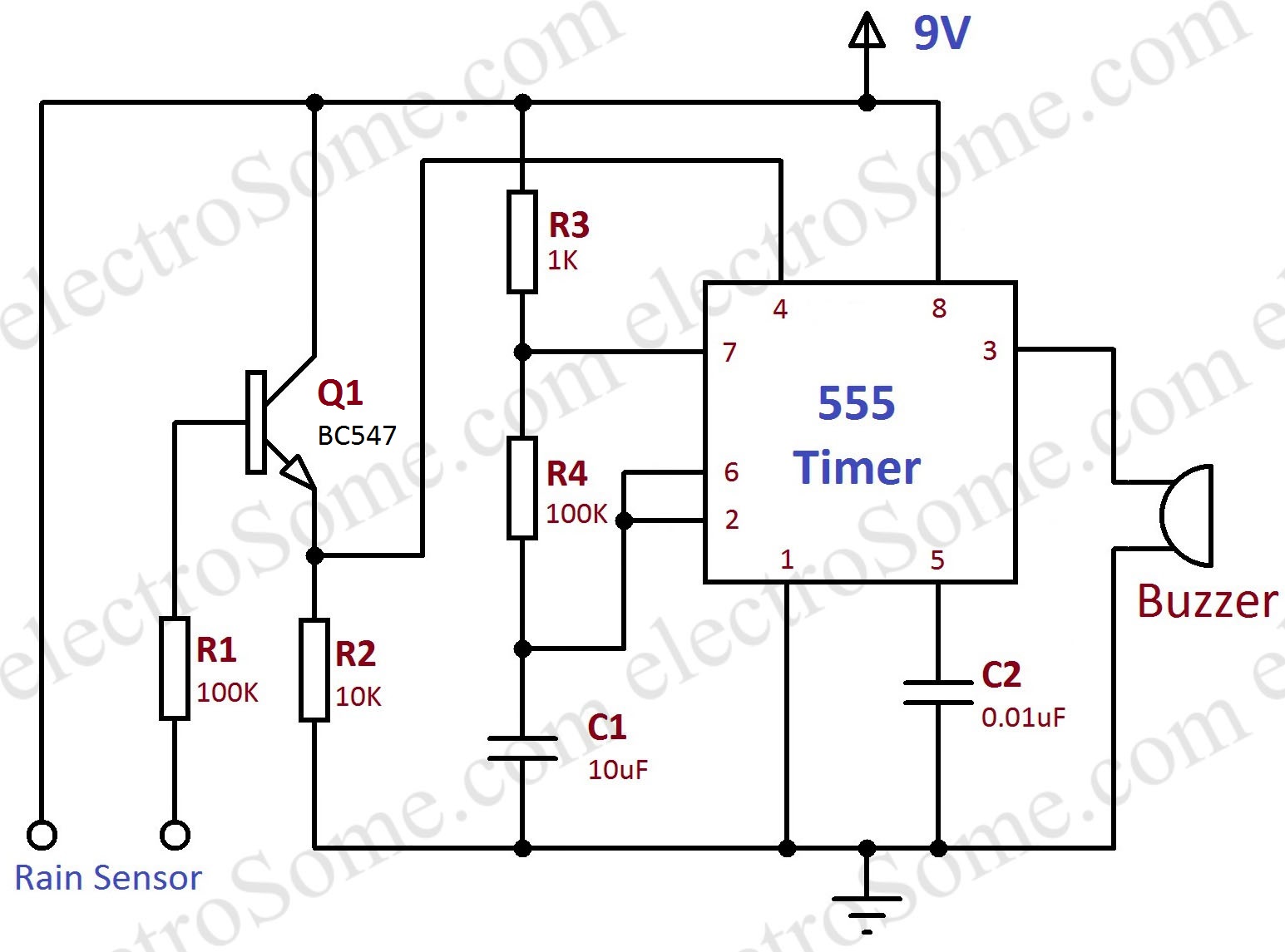
Rain Alarm using 555 Timer - Hobby Circuit from electrosome.com With 555 timer simple series takes advantage of the mode of the ic monostable multivibrator 555. 7 below, you'll see the circuit schematic of the 555 and the parts relevant to it. The schematic shows (3) circuits, because one circuit does not work well over the entire vcc range. The red section is the rc circuit that determines the pulse length. The contact of the relay finally drives any external ac load. The 555 timer ic is an integrated circuit (chip) used in a variety of timer, delay, pulse generation, and oscillator applications. This page contain electronic circuits about at category 555 timer circuit : Some important features of the 555 timer:
The contact of the relay finally drives any external ac load.
You can watch the following video or read the written tutorial below. A 555 timer has two comparators, which are. The above circuit uses a 555 timer u1 in mono stable mode. The output of uc (upper comparator) which is reset input to rs latch is high when the threshold input is high or. The 555 timer ic is an integrated circuit (chip) used in a variety of timer, delay, pulse generation, and oscillator applications.
555 Timer Tutorial - The Monostable Multivibrator from www.electronics-tutorials.ws Learn about the 555 timer and how it works in astable mode. The second circuit adds d1 to the emitter of q1 in order to increase vebo. Simple timer with 555 is one example of a simple timer and can be applied to electronic equipment. 555 timer, as the name specified, are the electronics circuits used for measuring time intervals. You can either follow the previous schematic or follow the breadboard wiring diagram below. Features of 555 timer ic. Each mode of operation indicates a circuit diagram and its output. With this information you will learn how how the 555 works and will have the experience to build some of the circuits below.
The block diagram of a 555 timer is shown in the above figure.
And now a full schematic of the 555 timer oscillator with single step and free run option. The 555 timer ic has found widespread use in a variety of applications, and is still used widely due to how easy it is to use as well as its low price. It includes all of the wiring diagrams and instructions you need to get started. Other circuitscircuits and schematics at next.gr. 7 below, you'll see the circuit schematic of the 555 and the parts relevant to it.
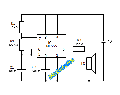
Audio Tone generator circuit using 555, 741 IC from mechatrofice.com However, d1 may be eliminated if we. This is a simple 555 timer long time delay circuit diagram. Other circuitscircuits and schematics at next.gr. You can watch the following video or read the written tutorial below. Learn about the 555 timer and how it works in astable mode. Lm555 timer internal circuit block diagram. The red section is the rc circuit that determines the pulse length. Look at the circuit diagram.
In this article, we will cover about 555 timers.
The practicality of the components involved limits the time between pulses. The 555 timer can provide time delays ranging from several minutes for one cycle of operation to many thousands of cycles per second. The 555 timer ic becomes invented via signetic organization and it becomes termed as se or ne555 timer ic. The red section is the rc circuit that determines the pulse length. 555 timer is a versatile and most usable device in the electronics circuits and designs which work for both stable and schematic & working principle of 555 timer ic. Now as shown in figure, there are eight pins although the schematic looks correct, this basic circuit may actually have a few negative aspects. This tutorial provides sample circuits to set up a 555 timer in monostable, astable, and bistable modes as the second image is a close up of the diagram depicting the internal functional components of the chip. 555 timer construction & block diagram. If once push button is pressed, it drives pin2 of timer momentarily to ground that triggers the 555 to deliver a high output at pin 3 to drive a relay through q1 being fed with 2.2k resistor. This is a simple 555 timer long time delay circuit diagram. However, d1 may be eliminated if we. In the schematic above, notice that the threshold pin and the trigger pin are connected to c1. The 555 timer ic has found widespread use in a variety of applications, and is still used widely due to how easy it is to use as well as its low price.
With this information you will learn how how the 555 works and will have the experience to build some of the circuits below 555 timer schematic. The schematic shows (3) circuits, because one circuit does not work well over the entire vcc range.